· Eduardo Vieira · Industrial Modernization · 5 min read
Control Panel Audit Before a Retrofit
Establish the actual panel baseline, energy boundaries, and acceptance path before changing wiring or controls.
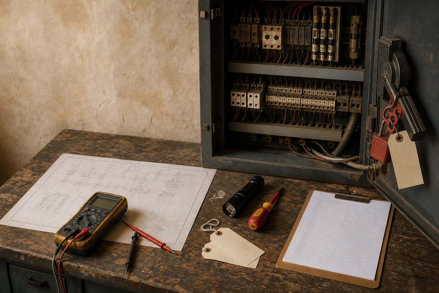
Control panel audit before a retrofit
A retrofit audit establishes what is actually installed, what may be changed, and what must remain under controlled safety ownership. It is not an energized-work procedure, a certification statement, or permission to open or modify a live panel. OSHA requirements cited here apply in the United States; the responsible party must verify local law, the applicable edition, and project-specific obligations.
Set the safety boundary first
Begin with the approved scope, responsible roles, operating state, and permitted evidence collection. Physical panel work requires qualified personnel, the site de-energization method, lockout/tagout, required PPE, and the approved absence-of-voltage verification process. Pushbuttons, selector switches, contactors, software states, and interlocks are not isolation devices.
Identify stored and backfeed energy before relying on an apparent off state. This article intentionally does not describe energized work methods. If a condition cannot be assessed safely within the approved boundary, record the gap and plan an authorized activity rather than improvising.
Compare as-found with as-built
Treat drawings as hypotheses until compared with the panel. Build an as-found baseline from dated photos, current drawings, BOMs, nameplates, I/O lists, firmware versions, controller and drive backups, parameter exports, network settings, and approved field-change records. Include terminal labels and cabinet identifiers that make later work traceable.
Mark every discrepancy: a spare relay added in the field, a substituted power supply, an unlabelled conductor, a changed drive parameter, or an undocumented network switch can alter retrofit risk. Preserve the source and revision of each record. A clean drawing does not prove the installed wiring, protection, or settings are equivalent.
Find every energy source
Inventory main and control power, DC supplies, UPS systems, drives, capacitors, pneumatic and hydraulic accumulators, gravity, springs, pressure, mechanical motion, external control supplies, and possible backfeed paths. Some sources remain present after the main disconnect opens. Stored energy needs the site-approved dissipation or restraint method before work begins.
Document energy source, isolation point, lockout point, verification method, downstream loads, and restoration owner. Do not assume a cabinet belongs to one supply because it has one visible disconnect. External field cabinets, shared neutrals, drive DC buses, and control transformers often create additional paths.
Review power, protection, and bonding
Record supply characteristics, disconnect arrangement, overcurrent protection, conductor condition and ratings, grounding, bonding, enclosure condition, and evidence relevant to available fault current. SCCR is not a generic label to copy from another panel: compare its applicability with the installed assembly, components, and available fault current using the applicable design record.
This review identifies questions for qualified design review; it does not certify a panel. Heat discoloration, loose mounting, damaged insulation, incompatible substitutions, or missing protective information are gaps requiring controlled disposition. Do not replace components merely because a catalog item appears similar.
Trace I/O, communications, and safety paths
Map field I/O to terminals, PLC channels, drawings, and intended function. Record communication links, gateways, addressing, shielding and grounding decisions where documented, and the owner of each interface. Check whether terminal labels and drawings allow a technician to distinguish control, safety, measurement, and auxiliary circuits.
Trace interlocks and safety circuits as their own boundary. A normal PLC input or HMI indication is not proof of a safety function. Preserve the approved safety configuration, device data, and validation evidence; changes to safety-related wiring or configuration need the lifecycle and acceptance process applicable to that function.
Assess maintainability before selecting a retrofit
Inventory obsolete devices, lead times, approved spares, unsupported firmware, thermal loading, cabinet space, environmental exposure, ingress protection, and service access. A retrofit scope that ignores wire bending space, heat dissipation, terminal capacity, or access for maintenance can create a new fault while removing an old one.
Rank gaps by credible consequence, exposure, uncertainty, and feasibility of mitigation. Separate mandatory corrections from useful modernization. The result is a defensible scope, not a shopping list built from visual age alone.
Produce reviewable deliverables
The audit package should contain the as-found evidence set, discrepancy register, energy inventory, risk-ranked gaps, proposed retrofit scope, preliminary BOM, assumptions, interfaces, and acceptance plan. State what has not been verified and who owns each follow-up action.
The acceptance plan should define FAT for the agreed build, SAT for the installed scope, SIT for interfaces in site context, and physical validation by the responsible disciplines. No one test replaces the others. A software simulation cannot prove installed wiring, protective devices, drive behavior, or physical safety response.
Plan rollback beyond the PLC file
Before a change, baseline PLC and HMI projects, wiring diagrams, hardware identities, firmware, drive parameters, network configuration, safety-device configuration, and approved backups. Define how to stop the work, restore previous wiring or hardware, restore parameters, and verify the restored condition.
Rollback must be practical during the maintenance window. Do not make irreversible field changes before the fallback is available. If a discovered discrepancy prevents safe restoration, stop and escalate rather than treating schedule pressure as an engineering criterion.
Review the completed package with operations, maintenance, controls, and electrical owners before release. Their agreement should identify remaining constraints, planned isolation boundaries, and the acceptance evidence required for each retrofit phase.
References and next steps
- OSHA, 1910.147: The control of hazardous energy.
- OSHA, 1910.333: Selection and use of work practices.
- IEC, IEC 60204-1: Safety of machinery—Electrical equipment of machines.
- UL Solutions, UL 508A Supplement SA component requirements.
- ISA, ISA-105 standards.
Continue with modern SCADA, RS-485 diagnosis, the OT checklist, and control-panel services.