· Industrial Protocols · 3 min read
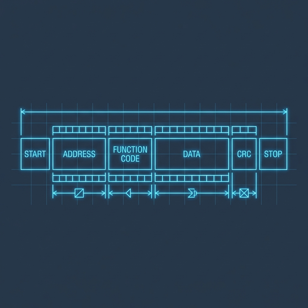
Modbus RTU Survival Guide: RS485, Noise & Troubleshooting
Is your Modbus network failing at night? A deep technical guide on termination, fail-safe biasing, grounding, and using an oscilloscope to see noise.
On paper, Modbus RTU over RS485 is simple. In practice, it is one of the biggest sources of headaches on the plant floor. Why? Because RS485 is a physical transmission line subject to the laws of electromagnetism, not just bits and bytes.
If your network has random “timeouts” or constant CRC errors, it’s not a bug in your code; it’s a physics problem. In this guide, we are going to “dissect” the physical layer.
1. RS485 Physics: Termination and Reflections
An RS485 cable must be treated as a transmission line. When a signal travels down a cable and reaches an open end, the energy “bounces” and returns, colliding with new data. This is called signal reflection.
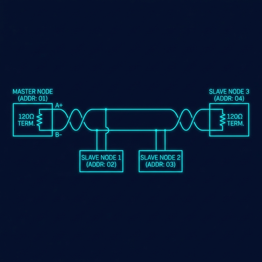
The Remedy: 120Ω Resistor
You must place a 120 Ohm resistor at the absolute physical ends of the bus (and only at the ends).
- Common Error: Putting resistors on every slave. This overloads the driver and burns the port.
- Effect: The resistor absorbs the energy at the end of the cable, eliminating the bounce.
2. Fail-Safe Biasing
When no device is transmitting, the bus enters a “high impedance” state. At this time, the differential voltage between A and B can be 0V. For an RS485 receiver, 0V is an indeterminate zone: ambient noise can be interpreted as false bits, generating “Frame Error” or garbage bytes.
Technical Implementation
You need to force a minimum differential voltage (typically >200mV) using pull-up and pull-down resistors:
- Pull-up (560Ω to 1kΩ) on the D+ (A) line to VCC (5V).
- Pull-down (560Ω to 1kΩ) on the D- (B) line to GND.
[!TIP] Many industrial converters (Moxa, Advantech) have internal DIP switches to enable this. Use them!
3. The Third Wire: Common Ground
“RS485 only needs two wires.” Lie. Although it is a differential protocol, transceivers have a common-mode voltage limit (usually -7V to +12V). If the ground of a PLC in Panel A is 50V apart from the ground of a sensor in Panel B, the RS485 chip will burn out or stop reading.
- Solution: Use shielded twisted-pair cable. Use the shield or a third conductor wire to join the
GorSGterminals of all devices.
4. Troubleshooting with Code
To diagnose, you need tools that don’t assume everything is fine. I’ve created a repository with utilities for this:
👉 GitHub: modbus-troubleshooting-toolkit
Slave ID Scanning (Practical Snippet)
If you don’t know the ID of a slave, you can use this Python snippet (requires pyserial and pymodbus):
from pymodbus.client import ModbusSerialClient

client = ModbusSerialClient(
    port='/dev/ttyUSB0',
    baudrate=9600,
    stopbits=1,
    bytesize=8,
    parity='N'
)

for slave_id in range(1, 248):
    result = client.read_holding_registers(0, 1, slave=slave_id)
    if not result.isError():
        print(f"Slave found at ID: {slave_id}!")
Sources and Deep Reading
- Texas Instruments: AN-1057 Ten Ways to Bulletproof RS-485 Interfaces (World reference technical document).
- Modbus.org: Modbus over Serial Line Specification & Implementation Guide V1.02.
- Maxim Integrated: RS-485 Glossary and Termination.
Still having problems? Check my Definitive Protocol Guide to see how to handle data once the physics are solved.